
Table of Contents >> Show >> Hide
- Why Curve Tracing Still Feels Like a Superpower
- Meet the Heathkit Curve Tracer: Charming, Capable, Slightly Opinionated
- What MOSFET Curves Actually Tell You
- The Two Classic Problems When You Ask a JFET-Friendly Tracer to Speak MOSFET
- The Hack in Plain English: Add Gate Offset + Add a Polarity Flip
- Using a MOSFET-Friendly Setup: Getting Curves That Actually Teach You Something
- How to Read the Display Like You’ve Been Doing It for Years
- Vintage Quirks: The Price of Analog Charm
- When Not to Hack: Safer Modern Alternatives That Still Deliver Curves
- Conclusion: A Vintage Tracer With a MOSFET Accent
- Bench Stories: What People Learn After “Hack Your Heathkit To Trace MOSFET Curves” (Experiences)
A multimeter can tell you a MOSFET is “alive.” A datasheet can tell you what it should do. But a curve tracer?
A curve tracer shows you what your specific part does, right now, on your benchwarts, quirks, and all. It’s the
difference between reading a restaurant menu and actually tasting the food.
If you’ve got a vintage Heathkit semiconductor curve tracer (especially the IT-1121 / IT-3121 family), you already own
a surprisingly capable machine for visualizing device behavior. The catch: these instruments were designed in an era when
“FET” often meant “JFET,” and MOSFETs were not the default power switch in basically everything that beeps.
With a thoughtful hack, you can make that Heathkit far more MOSFET-friendlywithout turning it into a science fair volcano.
Why Curve Tracing Still Feels Like a Superpower
Curve tracing is simple in concept: apply a controlled stimulus (voltage or current), measure the response, and plot the result.
The magic is that you don’t take one measurementyou take many points across a sweep, and you repeat that sweep across
several “steps” of another parameter. For MOSFETs, that usually means sweeping VDS while stepping VGS.
The result is the iconic “family of curves” that shows how drain current changes across operating regions.
Engineers use curve tracers to validate models, compare lots, catch counterfeits, check for damage from ESD, and confirm that a
“logic-level” MOSFET really behaves like one. Hobbyists use them for the same reason they own more screwdrivers than screws:
because the ability to see inside the problem is addictive.
Meet the Heathkit Curve Tracer: Charming, Capable, Slightly Opinionated
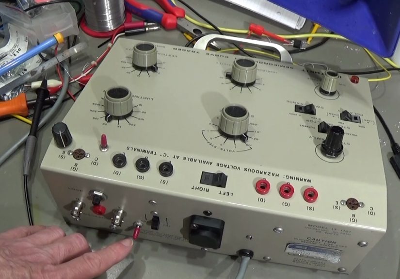
The Heathkit IT-1121 (and later IT-3121) is a classic bench companion that outputs X-Y signals for an oscilloscope display.
You feed the scope the tracer’s horizontal and vertical outputs, put the scope in X-Y mode, andboomcurves.
The Heathkit design also includes a step generator so you can create multiple traces per sweep (think: multiple gate steps).
Like many vintage instruments, it’s clever in how it accomplishes a lot with modest circuitry. It’s also very “of its time.”
And that time assumed your “FET testing” needs leaned heavily toward devices that want negative gate bias (hello, JFETs),
rather than enhancement-mode MOSFETs that usually want positive gate drive to do anything interesting.
What the stock unit does well
- Generates repeatable sweeps and steps that make curves easy to visualize on an analog scope.
- Provides switchable ranges and a workflow that’s fast for sorting and comparing parts.
- Turns “I think this MOSFET is weak” into “this curve is obviously sad.”
What it does less well (for MOSFETs)
- Gate-step behavior that’s optimized for JFET-style biasing can feel backward for MOSFETs.
- No built-in way to add a flexible VGS offset so your stepped waveform starts where a MOSFET actually turns on.
What MOSFET Curves Actually Tell You
MOSFET datasheets show a buffet of plots, but two are the headliners when you’re curve tracing:
output characteristics and transfer characteristics. Your Heathkit setup is mainly about output curves,
but you’ll end up thinking about transfer behavior constantly while you interpret what you see.
Output characteristics: ID vs VDS (with stepped VGS)
This is the classic family-of-curves plot. Each curve corresponds to a gate voltage step. You sweep VDS across a range and
watch how ID responds. The “knee” and the slope tell you a lot:
- Linear region: At low VDS, the MOSFET behaves resistively (useful for intuition about RDS(on)).
- Saturation region: Current becomes less sensitive to VDS (important for device behavior and modeling).
- Spacing between curves: Reveals effective transconductancehow strongly ID responds to changes in VGS.
Transfer characteristics: ID vs VGS (at fixed VDS)
Transfer curves answer the “how much gate voltage do I really need?” question. They also highlight the big misunderstanding
that ruins many beginner projects: VGS(th) is not the gate voltage you should drive in real circuits.
Threshold voltage is a definition point, not a recommendation. Curve tracing makes this obvious because you can watch how
dramatically the curves change as you step the gate.
Bonus reality checks: body diode, leakage, and “mystery meat” parts
A curve tracer is also great for:
- Body diode behavior: The built-in diode shows up immediately in the reverse direction.
- Leakage: A damaged MOSFET can look “fine” with a meter but show ugly leakage or odd curvature under sweep.
- Counterfeit detection hints: Not a guarantee, but “this curve doesn’t match the expected family” is a big clue.
The Two Classic Problems When You Ask a JFET-Friendly Tracer to Speak MOSFET
The popular “Hack Your Heathkit” approach focuses on two practical shortcomings that show up when you try to plot MOSFET curves
using the IT-1121’s FET mode.
Problem #1: No easy VGS offset
Enhancement MOSFETs often need a few volts on the gate before the curves become meaningfulespecially if you’re exploring
logic-level behavior versus “standard” gate-drive parts. If your gate staircase starts at 0 V and only steps a small amount,
you can end up with a set of curves that all look like “nothing… nothing… still nothing… oh hey, a tiny squiggle.”
An adjustable offset lets you shift that staircase upward so your steps land in the region you actually care about.
Problem #2: Gate-step polarity doesn’t match the drain sweep the way you want
Depending on how the instrument generates its step waveform and how the DUT is referenced, the gate staircase can end up
inverted relative to what makes intuitive sense for MOSFET output curves. Instead of “higher step = more current,” you might
get the opposite, or find that your preferred device polarity doesn’t line up with the step direction. That’s not fatal, but it’s
annoyingand it makes reading curves feel like you’re holding the datasheet upside down because “it’s art.”
The Hack in Plain English: Add Gate Offset + Add a Polarity Flip
The core hack is conceptually straightforward:
- Buffer the existing gate-step waveform so you don’t load the original circuitry.
- Sum that waveform with an adjustable DC offset (so the staircase can ride on top of a chosen baseline).
- Optionally invert the step waveform with a switch (so “up” on the gate steps corresponds to “up” on the curves).
- Keep it stable with reasonable op-amp choices, decoupling, and layout that won’t turn your curves into modern art.
In practice, people often implement this with a small op-amp board: one or more buffers, a summing stage to add the offset,
and an inverter or selectable polarity path. The charm is that you’re not rewriting the Heathkit’s identityyou’re giving it a
MOSFET “translation layer.”
Important safety note (not optional)
Vintage curve tracers can involve hazardous voltages and stored energy. Modifying mains-powered test equipment and working inside
the case can be dangerous. If you’re not trained to work safely around high voltage, treat this as an educational concept and use
modern low-voltage curve tracing alternatives instead (more on that below).
Using a MOSFET-Friendly Setup: Getting Curves That Actually Teach You Something
Once the gate offset and polarity are handled, the workflow becomes much more satisfying. The goal is to generate curves that are:
(1) readable, (2) repeatable, and (3) representative of the device without overheating it.
Start where the MOSFET wakes up
A gate offset lets you place your staircase so the lowest step is near the onset of conduction and the upper steps approach your
realistic drive range. This is especially revealing when comparing:
- Logic-level MOSFETs that show strong conduction at lower VGS, and
- “Standard” MOSFETs that look sleepy until higher VGS.
Keep heating from rewriting your experiment
MOSFET parameters shift with temperature. If you sweep slowly or drive too hard, the part heats and the curves drift. Many professional
systems use pulsed techniques specifically to reduce self-heating and keep the DUT closer to thermal equilibrium during measurement.
Even in a hobby context, thinking “short stimulus, reasonable duty cycle” helps keep your curves honest.
Use the curves to answer real questions
Curve tracing is most useful when you show up with a question and leave with an answer. For example:
- Does this MOSFET behave like the datasheet family-of-curves shape suggests, or is it suspiciously off?
- Do two “identical” MOSFETs actually match well enough to share current in a parallel setup?
- Is this part damaged (excess leakage, odd knees, inconsistent stepping), even though it passes a simple go/no-go test?
How to Read the Display Like You’ve Been Doing It for Years
The most common mistake is treating the curve tracer as a fancy pass/fail tester. It’s better than that. It’s a visual reasoning tool.
Here are the interpretations that pay off fast:
1) The “knee” tells you when the device transitions behavior
In the low-VDS region, the MOSFET looks more like a resistor whose value depends on VGS. As VDS rises, the curve bends into a region
where additional VDS doesn’t increase current as much. Where that bend occursand how sharp it isvaries by device and gate step.
2) The spacing between steps hints at transconductance
If equal gate steps produce wildly unequal changes in current, that tells you the device’s “gain-like” behavior isn’t uniform across the range.
That’s normal, but it matters for analog-ish uses, current regulation behavior, and device modeling.
3) Weird curvature is often a clue, not a mystery
- Flattening too early: could indicate limited drive, measurement range limits, or self-heating.
- Uneven step ordering: could indicate polarity confusion or a gate waveform issue.
- Unexpected conduction: could be the body diode, leakage, or a damaged gate oxide.
Vintage Quirks: The Price of Analog Charm
Part of the appeal of a Heathkit tracer is that it’s hands-on and understandable. The tradeoff is that it’s not a modern semiconductor parameter analyzer.
Expect to manage:
- Calibration and scaling: the X and Y outputs must be scaled to your scope settings.
- Contact resistance and fixtures: clip leads and sockets add resistance and inductance.
- Display preferences: analog scopes can make curves look beautifully “alive,” while digital scopes may require more setup to look clean.
None of these are deal-breakers. They’re just the tax you pay for using a tool that predates the phrase “firmware update.”
When Not to Hack: Safer Modern Alternatives That Still Deliver Curves
If your priority is curve tracing MOSFET behavior without working inside high-voltage vintage gear, there are modern approaches that are
safer and often cheaper than chasing rare parts for an older instrument.
USB lab tools with curve tracer modes
Some modern mixed-signal lab tools (with waveform generators and analog inputs) can be configured as curve tracers for diodes and transistors,
and can visualize I-V behavior effectively within their voltage/current limits. These are great for small-signal work and educational exploration.
SMU-based curve tracing (the “grown-up” method)
Source Measure Units (SMUs) and SMU software can build MOSFET I-V curve families with controlled sweeps and protection limits.
Professional workflows often use pulsed I-V methods to prevent self-heating and stay within safe operating areas.
Why the Heathkit hack still matters
The Heathkit approach sits in a sweet spot: more “real curve tracer” than many ultra-budget testers, and far more affordable than
full-blown semiconductor analyzersespecially if you already own the unit. The hack is about pushing a capable vintage platform into
modern relevance.
Conclusion: A Vintage Tracer With a MOSFET Accent
Hacking a Heathkit curve tracer to better handle MOSFETs is less about chasing perfection and more about unlocking clarity.
Add a gate offset so your steps land where MOSFETs actually conduct. Add a polarity option so your curves read naturally.
Then use the instrument the way it deserves to be used: as a visual truth machine that helps you compare devices, spot damage,
and develop intuition that no spreadsheet can teach.
Whether you keep it vintage and minimal or pair it with modern measurement habits, the payoff is the same: you stop guessing what
your MOSFET is doingand you start seeing it.
Bench Stories: What People Learn After “Hack Your Heathkit To Trace MOSFET Curves” (Experiences)
After the first successful MOSFET curve appears on the screen, the emotional arc is surprisingly predictable: excitement, confidence,
overconfidence, confusion, and then genuine understanding. The excitement comes from the fact that a family of curves feels like a secret window
into the silicon. The confidence comes from thinking, “I can measure anything now.” The overconfidence arrives about ten minutes later, when someone
tries a bigger MOSFET, a bigger sweep, or a different package style and learns that curves don’t just show device behaviorthey also reveal test setup
behavior. That’s the humbling part. It’s also the best part.
One of the most common “aha” moments is how misleading threshold voltage can be in everyday thinking. People will often say a MOSFET is “a 2–4 V gate part”
because they’ve seen a VGS(th) number in a datasheet. Then they trace curves and realize the device may technically begin to conduct at that voltage but still
behaves nothing like a low-resistance switch until the gate is driven significantly higher. Seeing the current curves “wake up” slowlythen acceleratedoes more
to fix this misunderstanding than any paragraph ever written (including this one, yes, even this one).
Another frequent experience: the first time someone compares two MOSFETs that were supposed to be the same and discovers they aren’t. Sometimes it’s normal
part-to-part variation. Sometimes it’s temperatureone device was traced later in the session when everything was warmer. Sometimes it’s contact resistance and
lead setup. But occasionally it’s the dramatic kind of mismatch that hints at a counterfeit or a mislabeled part. Curve tracing doesn’t automatically prove fraud,
but it makes suspicious behavior painfully obvious. People often describe this as the moment the curve tracer “paid for itself,” even if the tracer was already
on the bench for years.
Then there’s the “scope personality” discovery. Analog scopes often make curves look smooth and stable, which feels like magic until you realize the instrument is
doing a lot of perceptual smoothing for you. Digital scopes can show jitter, sampling artifacts, and weird-looking traces if the settings aren’t friendly to X-Y work.
The experience many folks report is that once they get the scope dialed inproper coupling, sensible scaling, stable triggering (when applicable), and reasonable
averagingthey begin trusting the curve shape again. That process teaches a transferable skill: measurement is not just the DUT; it’s the DUT plus the instrument
plus the setup plus the operator. The operator part is usually the funniest (and most fixable) one.
A surprisingly practical lesson comes from the MOSFET gate itself. People learn to respect the gate as a high-impedance, easy-to-annoy node. If a device behaves
inconsistently, it’s not always “the MOSFET is bad.” Sometimes it’s a floating gate, an ESD event, or a leaky path in the fixture. The curve tracer turns these into
visible symptoms: curves that don’t step evenly, traces that drift, or conduction that appears when it shouldn’t. Once someone has seen a “ghost curve” caused by a
gate that isn’t being controlled cleanly, they tend to become much better at handling and biasing MOSFET gates in real circuits. That’s growth. Annoying growth,
but growth.
Finally, a lot of people report the same emotional payoff: curve tracing makes datasheets feel less abstract. Instead of “Figure 1: Typical Output Characteristics”
being a mystical plot from a distant land, it becomes a familiar shape that you can reproduce, interpret, and compare. The Heathkit hack is often remembered less as
“that time I modified a vintage instrument” and more as “the moment MOSFETs stopped being mysterious.” And that’s the kind of bench experience that stickslong after
the novelty of the first squiggle wears off.