
Table of Contents >> Show >> Hide
- What Is a Capacitor Marking?
- How to Read a Capacitor: 13 Steps
- Step 1: Identify the Type of Capacitor
- Step 2: Make the Capacitor Safe to Handle
- Step 3: Look for Plain Printed Values First
- Step 4: Understand pF, nF, and µF
- Step 5: Decode the Three-Digit Capacitor Code
- Step 6: Read Decimal Markings and “R” Codes
- Step 7: Decode Tolerance Letters
- Step 8: Read the Voltage Rating
- Step 9: Check Polarity Markings Carefully
- Step 10: Understand Ceramic Dielectric Codes
- Step 11: Read Color Bands on Older Capacitors
- Step 12: Watch for Safety Capacitor Markings
- Step 13: Verify with a Meter or Datasheet When in Doubt
- Common Capacitor Reading Examples
- Quick Capacitor Code Reference Table
- Common Mistakes When Reading Capacitors
- Practical Experience: Lessons from Reading Capacitors at the Workbench
- Conclusion
- SEO Tags
Capacitors are tiny electronic parts with a surprisingly dramatic personality. They store electrical energy, smooth out voltage, help motors start, tune radio circuits, filter noise, and occasionally make beginners squint at a mysterious code like 104K as if it were a secret message from a spy movie. The good news is that learning how to read a capacitor is not difficult once you know what the numbers, letters, stripes, and symbols mean.
This guide walks you through how to read a capacitor in 13 practical steps, including capacitance value, tolerance, voltage rating, polarity, ceramic capacitor codes, electrolytic markings, SMD capacitor codes, and safety labels. Whether you are repairing a power supply, sorting a parts drawer, replacing an old capacitor, or trying to understand why one tiny beige disc says “103” and another says “224,” this article will help you decode the little rascals without needing a magnifying glass, a chant, or a degree in wizardry.
Important note: Capacitors can hold a charge after power is removed. For low-voltage hobby circuits, the risk is usually small, but capacitors inside power supplies, amplifiers, microwaves, HVAC systems, camera flashes, and other mains-powered equipment can be dangerous. Always disconnect power, verify voltage with a meter, and discharge capacitors safely before handling them.
What Is a Capacitor Marking?
A capacitor marking is the printed code, number, color band, stripe, or symbol that tells you the component’s electrical identity. The most important details are usually capacitance, voltage rating, tolerance, and polarity. Larger capacitors often print these details plainly, such as “470µF 25V.” Smaller ceramic, film, and surface-mount capacitors may use shorthand codes because there is not enough room for a full biography on a component smaller than a grain of rice.
The key is to read the capacitor in context. A big aluminum cylinder is probably an electrolytic capacitor. A tiny brown disc is often ceramic. A rectangular yellow block may be film. A small black or tan SMD part could be tantalum or ceramic, and that difference matters because tantalum capacitors are polarized while most ceramic capacitors are not.
How to Read a Capacitor: 13 Steps
Step 1: Identify the Type of Capacitor
Before decoding any number, look at the capacitor’s shape and construction. Electrolytic capacitors are usually cylindrical and often have a plastic sleeve. They commonly show capacitance in microfarads, such as 10µF, 100µF, or 1000µF. Ceramic capacitors are often small discs or rectangular MLCC chips and may use codes like 102, 103, or 104. Film capacitors are commonly box-shaped or dipped and may use printed values or three-digit codes. Tantalum capacitors may look like small drops or molded SMD blocks and usually have polarity markings.
This first step prevents a classic mistake: reading a stripe the wrong way. On many aluminum electrolytic capacitors, the stripe marks the negative lead. On many tantalum capacitors, a stripe or bar marks the positive side. Same visual idea, opposite meaning. Electronics likes to keep us humble.
Step 2: Make the Capacitor Safe to Handle
If the capacitor is loose in a parts drawer, you can usually inspect it directly. If it is installed in a circuit, safety comes first. Turn off and unplug the device. Do not assume the capacitor is empty just because the equipment is off. Use a multimeter to check voltage across the capacitor terminals. If voltage remains, discharge it using an appropriate resistor and insulated leads. Avoid shorting high-value or high-voltage capacitors with a screwdriver; it may create sparks, damage the capacitor, pit the tool, or give you the kind of surprise that makes coffee unnecessary.
For high-voltage gear, consult service documentation or a qualified technician. Reading a capacitor is useful; becoming part of the circuit is not.
Step 3: Look for Plain Printed Values First
Many capacitors are friendly and simply tell you what they are. A marking such as 220µF 16V means the capacitor has a capacitance of 220 microfarads and a maximum working voltage of 16 volts. A marking such as 4.7µF 50V means 4.7 microfarads and 50 volts. If you see nF, that means nanofarads; if you see pF, that means picofarads.
Sometimes the micro symbol appears as “u” instead of “µ,” especially in plain-text markings. So 10uF and 10µF mean the same thing. Older parts may use “mfd” for microfarads, which can confuse modern readers because “m” often means milli. In capacitor repair work, especially vintage radios, “mfd” usually means µF.
Step 4: Understand pF, nF, and µF
Capacitance values are often expressed in three common units:
- 1 µF = 1,000 nF = 1,000,000 pF
- 1 nF = 1,000 pF
- 0.1 µF = 100 nF = 100,000 pF
This conversion matters because capacitor codes are usually based on picofarads. For example, the common code 104 equals 100,000 pF, which is also 100 nF or 0.1 µF. A beginner may think 104 means 104 pF, but the third digit is not a normal digit; it is a multiplier. That tiny “4” is doing more lifting than a gym influencer on leg day.
Step 5: Decode the Three-Digit Capacitor Code
The most common capacitor code uses three digits. The first two digits are the significant figures. The third digit tells you how many zeros to add. The result is in picofarads.
Use this formula:
First two digits + number of zeros shown by third digit = value in pF
Examples:
- 101 = 10 followed by 1 zero = 100 pF
- 102 = 10 followed by 2 zeros = 1,000 pF = 1 nF
- 103 = 10 followed by 3 zeros = 10,000 pF = 10 nF
- 104 = 10 followed by 4 zeros = 100,000 pF = 100 nF = 0.1 µF
- 224 = 22 followed by 4 zeros = 220,000 pF = 220 nF = 0.22 µF
- 473 = 47 followed by 3 zeros = 47,000 pF = 47 nF = 0.047 µF
Once you understand this pattern, capacitor labels stop looking random. They still look tiny, but at least they become tiny and meaningful.
Step 6: Read Decimal Markings and “R” Codes
Some capacitors use a letter as a decimal point. For very small values, you may see markings such as 4R7 or 2R2. In this style, “R” represents the decimal point, so 4R7 means 4.7 pF or sometimes 4.7Ω in resistor markings, depending on the component. On capacitors, context is everything.
You may also see values like 4p7, which means 4.7 pF. A marking like n47 may mean 0.47 nF, while u1 may mean 0.1 µF. These styles are more common in certain film, ceramic, or older European-style markings. If the part is unusual or mission-critical, confirm with the datasheet or a capacitance meter.
Step 7: Decode Tolerance Letters
Capacitor tolerance tells you how far the real value may vary from the printed value. A capacitor marked 0.1µF with ±10% tolerance may measure anywhere from 0.09µF to 0.11µF and still be considered within specification.
Common tolerance letters include:
- F = ±1%
- G = ±2%
- J = ±5%
- K = ±10%
- M = ±20%
- Z = often +80% / -20% on some ceramic capacitors
For example, 104K means 100,000 pF, or 0.1µF, with ±10% tolerance. 473J means 47,000 pF, or 47nF, with ±5% tolerance. In timing, audio, RF, and precision circuits, tolerance can matter a lot. In general decoupling circuits, a wider tolerance is often acceptable.
Step 8: Read the Voltage Rating
The voltage rating is the maximum voltage the capacitor is designed to handle continuously under normal operating conditions. A capacitor marked 25V should not be used in a 30V circuit. In fact, it is common practice to choose a capacitor with a voltage rating comfortably higher than the circuit voltage. For a 12V circuit, a 16V or 25V capacitor may be used depending on the application, ripple, temperature, and reliability requirements.
Large electrolytic capacitors usually print voltage directly, such as 16V, 25V, 50V, or 400V. Smaller capacitors may use short voltage codes, and these are not always universal across manufacturers. If a voltage marking is unclear, do not guess in power circuits. Check the datasheet or replace the part with one that clearly meets the circuit requirement.
Step 9: Check Polarity Markings Carefully
Polarity is one of the most important things to read on a capacitor. Non-polarized capacitors, such as most ceramic and film capacitors, can be installed either way. Polarized capacitors, such as aluminum electrolytic and many tantalum capacitors, must be installed in the correct orientation.
On many radial aluminum electrolytic capacitors, the longer lead is positive and the stripe on the body marks the negative side. The stripe often contains minus signs. On many circuit boards, the positive pad may be marked with a plus sign, while the negative side may be shaded or indicated by the footprint design.
Tantalum capacitors require extra attention because the stripe often marks the positive terminal, not the negative terminal. This is one of the easiest polarity traps in electronics. If you are replacing a tantalum capacitor, compare the old part, the board marking, and the datasheet before soldering.
Step 10: Understand Ceramic Dielectric Codes
Ceramic capacitors may include codes such as C0G, NP0, X7R, X5R, or Y5V. These describe the dielectric material and its behavior over temperature and voltage. A C0G/NP0 capacitor is very stable and is often used in timing, RF, oscillator, and precision circuits. X7R and X5R capacitors offer more capacitance in a small size and are widely used for decoupling and filtering. Y5V capacitors can provide high capacitance cheaply, but their actual capacitance may change significantly with temperature and applied voltage.
In simple terms: C0G is the calm accountant, X7R is the reliable generalist, and Y5V is the bargain-bin party guest who may or may not behave when conditions change.
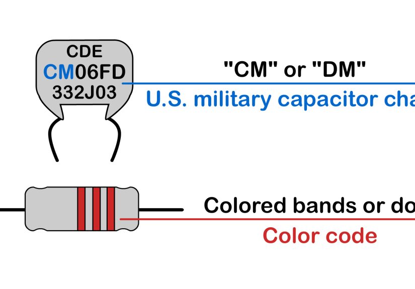
Step 11: Read Color Bands on Older Capacitors
Older capacitors may use color bands or dots, similar to resistor color codes. The first color usually represents the first digit, the second color the second digit, and the third color the multiplier. Additional bands may indicate tolerance, voltage, or temperature characteristics. These markings are common on vintage mica, ceramic, and tubular capacitors.
Because different old capacitor families used different systems, color-coded capacitors can be tricky. If you are restoring vintage electronics, compare the part to a known chart, the schematic, and the circuit location. Also remember that old paper and electrolytic capacitors may drift, leak electrically, or fail even if you can read their markings perfectly.
Step 12: Watch for Safety Capacitor Markings
Capacitors used across or from the AC mains often carry safety class markings such as X1, X2, Y1, or Y2. These are not ordinary capacitors. X-rated capacitors are typically used across the line, while Y-rated capacitors are used from line to ground or neutral to ground in applications where failure behavior is especially important.
If you find an X2 capacitor in a power input filter, replace it with another X2 safety-rated capacitor of the correct value and voltage class. Do not substitute a random film capacitor just because the capacitance matches. A safety capacitor is designed and certified for a specific job, and that job includes not turning your project into a smoke machine.
Step 13: Verify with a Meter or Datasheet When in Doubt
Markings are helpful, but they are not magic. Capacitors may be damaged, mislabeled, aged, counterfeit, or too worn to read. A digital multimeter with a capacitance function can confirm the approximate value. For better accuracy, use an LCR meter. When replacing parts in critical equipment, compare the marking against the manufacturer datasheet, especially for voltage rating, ESR, ripple current, temperature rating, package size, and polarity.
For electrolytic capacitors in power supplies, matching capacitance and voltage is not always enough. ESR and ripple current can affect performance and lifespan. For ceramic capacitors, the package size and dielectric type can affect how much capacitance remains under DC bias. In other words, two capacitors can have the same “10µF” label and behave differently in the real world.
Common Capacitor Reading Examples
Example 1: 104K
The first two digits are 10. The third digit is 4, so add four zeros. That gives 100,000 pF, which equals 100 nF or 0.1µF. The letter K means ±10% tolerance. Therefore, 104K = 0.1µF ±10%.
Example 2: 220µF 35V
This one is straightforward. The capacitance is 220 microfarads, and the maximum working voltage is 35 volts. If it is an electrolytic capacitor, check the stripe and lead length for polarity before installing it.
Example 3: 473J
The code 473 means 47 followed by three zeros, or 47,000 pF. That converts to 47 nF or 0.047µF. The J means ±5% tolerance. Therefore, 473J = 47nF ±5%.
Example 4: 2R2
The “R” works as a decimal point. In capacitor markings, 2R2 usually means 2.2 pF. If the component is tiny and unmarked beyond that, verify with a meter or datasheet.
Example 5: 10µF 16V with a Negative Stripe
This is likely an aluminum electrolytic capacitor. The value is 10 microfarads, the voltage rating is 16 volts, and the stripe marks the negative terminal. The longer lead, if untrimmed, usually marks the positive terminal.
Quick Capacitor Code Reference Table
| Marking | Capacitance in pF | Equivalent Value |
|---|---|---|
| 101 | 100 pF | 100 pF |
| 102 | 1,000 pF | 1 nF |
| 103 | 10,000 pF | 10 nF / 0.01µF |
| 104 | 100,000 pF | 100 nF / 0.1µF |
| 224 | 220,000 pF | 220 nF / 0.22µF |
| 474 | 470,000 pF | 470 nF / 0.47µF |
Common Mistakes When Reading Capacitors
The first mistake is confusing capacitor code values with normal numbers. A 104 capacitor is not 104 pF; it is 100,000 pF. The second mistake is ignoring voltage rating. A correct capacitance with too-low voltage rating is still the wrong part. The third mistake is reversing polarity on electrolytic or tantalum capacitors. That can cause leakage, overheating, venting, or complete failure.
Another common mistake is replacing a safety capacitor with a standard capacitor. If the old component says X2, the replacement must also be properly safety-rated. Finally, beginners sometimes assume all 10µF capacitors are interchangeable. In reality, package size, dielectric, ESR, ripple current, temperature rating, and expected lifespan may matter depending on the circuit.
Practical Experience: Lessons from Reading Capacitors at the Workbench
The first time you try to read a capacitor, it may feel like the component is deliberately hiding information from you. That is especially true when you are working with older boards, dusty power supplies, or tiny SMD parts that appear to have been labeled by an ant with a laser printer. The best habit is to slow down and gather clues instead of forcing a quick answer.
One practical experience that helps is sorting capacitors by type before sorting by value. Put aluminum electrolytics in one group, ceramic discs in another, film capacitors in another, and SMD parts in a separate tray. Once the types are separated, the markings become easier to interpret. Electrolytics usually give you plain values. Ceramic and film capacitors often require code conversion. Tantalums demand careful polarity checking. This simple sorting step prevents many mistakes.
Another useful habit is to write conversions on small labels or storage drawers. For example, label one compartment “104 = 0.1µF,” another “103 = 10nF,” and another “102 = 1nF.” After seeing the same codes repeatedly, you will memorize them naturally. The 104 capacitor is especially common in digital circuits as a decoupling capacitor near integrated circuit power pins. Once you recognize it, you will start spotting it everywhere, like a tiny beige celebrity.
When replacing capacitors during repairs, take photos before removing anything. A smartphone photo can preserve polarity orientation, board markings, and component location. This is extremely helpful when the capacitor is damaged or when the board silkscreen is unclear. Mark the negative side of electrolytic capacitors on your notes before desoldering. For tantalum capacitors, double-check whether the stripe indicates positive. Do not rely on memory alone; memory is a wonderful thing until flux fumes and five similar-looking parts join the party.
A meter also becomes your friend. A capacitance meter will not tell you every performance detail, but it can catch obvious mix-ups. If a part marked 104 reads close to 100nF, you are probably on the right track. If an old electrolytic marked 100µF reads far below value or shows suspicious behavior, it may be time to replace it. In repair work, visual inspection also matters. Bulging tops, leaking electrolyte, cracked ceramic bodies, burned film cases, or corroded leads are warning signs.
Finally, experience teaches humility. Capacitor markings are mostly standardized, but not perfectly universal. Some manufacturer voltage codes, SMD markings, and vintage color systems require datasheets. When the circuit is low-voltage and non-critical, you can often make a confident identification from the marking. When the circuit is high-voltage, safety-related, expensive, or mission-critical, verify everything. Good electronics work is not about guessing faster; it is about checking smarter.
Conclusion
Learning how to read a capacitor is a practical skill that pays off in electronics repair, DIY projects, circuit design, and component organization. Start by identifying the capacitor type, then read the printed value, decode three-digit markings, convert between pF, nF, and µF, check tolerance letters, confirm voltage rating, and inspect polarity. For ceramic capacitors, understand dielectric codes like C0G, X7R, and Y5V. For electrolytic and tantalum capacitors, polarity is not optional. For safety capacitors, the X or Y rating must be respected.
Once you learn the pattern, capacitor markings become much less mysterious. A code like 104K stops looking like a robot password and starts reading clearly as 0.1µF with ±10% tolerance. That is the moment when the parts drawer becomes less chaotic, repairs become safer, and your electronics confidence gets a very satisfying voltage boost.