
Table of Contents >> Show >> Hide
- What Is an AVR TPI Programmer?
- Why Use an Arduino as a USB AVR TPI Programmer?
- How TPI Differs From Classic AVR ISP
- Basic Parts You Need
- Preparing the Arduino
- Using AVRDUDE With a TPI Target
- Voltage and Signal Safety
- Common Problems and How to Diagnose Them
- Practical Example: Programming an ATtiny10
- Why This Project Is Still Useful
- Best Practices for a Reliable Arduino TPI Programmer
- Limitations You Should Understand
- SEO-Friendly Summary for Makers
- Extra Field Notes: Real-World Experiences With a USB Arduino Into AVR TPI Programmer
- Conclusion
Turning a USB Arduino into an AVR TPI programmer is one of those projects that feels delightfully illegal, even though it is perfectly wholesome. You start with a familiar Arduino board, add a little firmware, connect a few careful wires, and suddenly that humble blue board is speaking Tiny Programming Interface, better known as TPI. In other words, your Arduino graduates from blinking LEDs to programming tiny AVR microcontrollers that look like they were designed by someone trying to fit a computer into a breadcrumb.
The idea is simple: many classic AVR chips can be programmed through ISP, but some very small AVR devices, such as the ATtiny4, ATtiny5, ATtiny9, and ATtiny10 family, use TPI instead. These chips have so few pins that the familiar MOSI, MISO, SCK, RESET, VCC, and GND layout is not practical in the same way. TPI solves that by using a compact physical interface: reset, clock, and a bidirectional data line, along with power and ground. It is small, efficient, and slightly fussylike a cat that only respects you after you read the datasheet.
What Is an AVR TPI Programmer?
An AVR TPI programmer is a tool that lets your computer write firmware to certain low-pin-count AVR microcontrollers. TPI stands for Tiny Programming Interface. It was created for selected small AVR chips where a full ISP interface would consume too many pins. Instead of separate data-in and data-out lines, TPI uses a bidirectional data pin, a clock pin, and reset control to enter programming mode.
In practical terms, a TPI programmer acts as a translator. Your computer sends programming commands through USB. The programmer converts those commands into the timing and signaling that the target AVR chip understands. The target chip receives the program, stores it in flash memory, and then behaves according to the new firmware. If everything goes well, the chip runs your code. If everything goes badly, you learn humility, wiring discipline, and possibly new words.
Why Use an Arduino as a USB AVR TPI Programmer?
The main reason is convenience. Many makers already have an Arduino Uno, Nano, Leonardo, Micro, or similar board somewhere on the bench. Using an Arduino as a programmer avoids buying a dedicated AVR tool just to work with a handful of tiny chips. For students, hobbyists, repair tinkerers, and small-batch prototype builders, that is a very attractive deal.
A USB Arduino also gives you a comfortable connection to the computer. Instead of dealing with parallel ports from the ancient kingdom of beige desktops, you plug in a USB cable, select the correct port, and use software such as AVRDUDE or a compatible programming utility. The Arduino handles the low-level timing, while your computer sends the firmware file.
The Big Benefit: Programming Tiny AVR Chips
Tiny AVR chips are useful when a project needs simple control logic without wasting space, money, or power. An ATtiny10, for example, can handle small tasks such as LED effects, button logic, sensor reading, simple timing, or lightweight control routines. It is not a full development board hiding in a six-pin package, but it is surprisingly capable when used correctly.
The challenge is that these chips are not programmed like the larger ATmega328P found in a classic Arduino Uno. A normal ArduinoISP setup is excellent for many ISP-based AVR devices, but TPI devices need a different protocol. That is where the USB Arduino-to-TPI programmer project becomes useful.
How TPI Differs From Classic AVR ISP
Classic AVR ISP usually uses separate SPI-style lines: MOSI, MISO, SCK, and RESET, plus power and ground. TPI, by contrast, is designed for chips with extremely limited pin counts. It uses TPICLK for the clock, TPIDATA as a bidirectional data line, and RESET to place the chip in programming mode.
This difference matters because you cannot simply wire a TPI chip exactly like a normal ISP chip and expect it to behave. The programmer firmware must understand TPI commands, line direction changes, memory access behavior, and timing. The hardware is simple, but the protocol is not just “ISP with fewer wires.” It is its own little creature, wearing tiny shoes.
Basic Parts You Need
A typical USB Arduino into AVR TPI programmer setup requires only a modest collection of parts. You need an Arduino-compatible board, a USB cable, jumper wires, the target AVR chip, a breadboard or small programming fixture, and usually a few resistors for safer signal handling. A capacitor may be useful in some setups to prevent auto-reset on certain Arduino boards, depending on how the firmware and host software are configured.
You also need software. At minimum, that includes programmer firmware for the Arduino and a host-side tool capable of sending the compiled firmware to the target chip. AVRDUDE is commonly used in AVR programming workflows because it supports many AVR devices and programmer types. Some projects use custom firmware that behaves like a known programmer protocol, while others use dedicated host scripts or patched tools.
Typical Connections
The exact pin mapping depends on the firmware you choose, but the target-side connections usually include VCC, GND, RESET, TPICLK, and TPIDATA. Some layouts place these on a six-pin header so the physical connector feels familiar even though the protocol is different from ISP. The important point is not the shape of the connectorit is making sure each signal reaches the correct pin on the target AVR.
Always check the target chip datasheet before wiring. The ATtiny10 family, for example, uses pins in a compact package where it is painfully easy to rotate the chip, count pins backward, and spend half an hour debugging a problem that is actually just chip yoga. Mark pin one, verify power, and keep a copy of the pinout open while wiring.
Preparing the Arduino
The Arduino must run firmware that knows how to behave as a TPI programmer. This is different from uploading a normal sketch that blinks an LED. The firmware turns the Arduino into a bridge between USB serial communication and the TPI lines connected to the target chip.
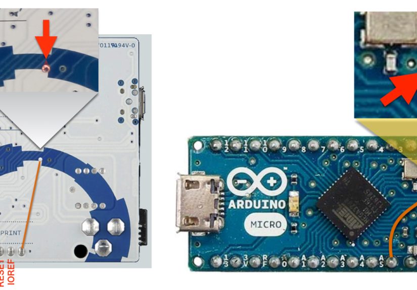
On some Arduino boards, the USB interface and main microcontroller are separate. On others, such as boards based on the ATmega32U4, USB is handled directly by the main chip. The setup process depends on the board and firmware project. Some approaches involve uploading a sketch through the Arduino IDE. Others involve flashing firmware more directly. Either way, the goal is the same: your Arduino stops acting like a general development board and starts acting like a programmer.
Firmware Matters
The most important choice is the programmer firmware. Good firmware should clearly document supported target chips, required baud rate, wiring, and host command examples. If the project supports both ISP and TPI, pay attention to any mode-selection jumper or configuration pin. Accidentally using ISP mode when the target expects TPI is like ordering pizza in Morse code: technically full of signals, practically not dinner.
Look for firmware that supports the device family you plan to program. Common TPI targets include ATtiny4, ATtiny5, ATtiny9, ATtiny10, and in some cases related tiny AVR devices such as ATtiny20 and ATtiny40. Device support is not something to guess. Check it before building your programming adapter.
Using AVRDUDE With a TPI Target
Once the Arduino is prepared and the target chip is wired, the host computer needs to send firmware to the programmer. AVRDUDE is often used for this job. A command typically identifies the part number, programmer type, serial port, baud rate, and firmware file.
On Windows, the port may look like COM3 or COM7. On macOS or Linux, it may look like a device path under /dev. The exact programmer type depends on the Arduino firmware. Some projects emulate an existing protocol; others require specific support. Do not copy command lines blindly from a random forum post unless you also enjoy mystery smoke and emotional support snacks.
Reading Before Writing
A smart first test is reading the target signature, if your software and programmer support it. This confirms that power, ground, reset, clock, data, firmware, port settings, and device selection are all reasonably correct. If signature reading fails, do not immediately blame the chip. Check wiring, baud rate, chip orientation, voltage level, and whether the reset line is being controlled properly.
Voltage and Signal Safety
Voltage compatibility is a big deal. Many Arduino boards operate at 5V, while some target circuits may operate at lower voltages. If the target AVR is powered at 5V, a 5V Arduino is usually straightforward. If the target is a 3.3V circuit, level shifting may be needed to avoid damaging the device.
For a simple breadboard programming setup, powering the target from the Arduino 5V pin is common, but it is not always the best choice. If the target circuit has its own power supply, confirm whether the programmer should provide power or only sense the target voltage. Accidentally connecting two power sources together can create a very educational but unpleasant afternoon.
Common Problems and How to Diagnose Them
The Programmer Is Not Detected
If your computer does not detect the Arduino, start with the boring things. Try another USB cable, confirm the board appears in the device manager or serial port list, and make sure drivers are installed where needed. Many “dead programmer” problems are secretly “charging cable with no data lines” problems. USB cables are the pranksters of the electronics drawer.
The Target Signature Cannot Be Read
Signature read failure usually means the programmer cannot communicate with the target. Check VCC and GND first. Then verify TPIDATA, TPICLK, and RESET. Confirm that the target chip is supported by the selected command and programmer firmware. Also check whether any external circuitry is loading the programming pins. LEDs, sensors, pull-ups, or other attached components can interfere with communication.
Writing Fails Halfway
Intermittent write failures can come from unstable power, loose jumper wires, incorrect baud rate, poor breadboard contacts, or timing issues. Keep wires short, use a stable supply, and avoid running programming lines across a messy breadboard full of other signals. Tiny chips are not impressed by spaghetti wiring, even when the spaghetti is color-coded.
Practical Example: Programming an ATtiny10
Imagine you want an ATtiny10 to drive a small LED pattern in a minimalist project. The chip is cheap, small, and perfect for the job. You write a simple C program, compile it into a HEX file, and use your Arduino-based TPI programmer to flash it.
The workflow looks like this: prepare the Arduino with TPI programmer firmware, place the ATtiny10 on a breadboard or adapter, wire the TPI lines, connect USB, verify communication, then write the HEX file. After programming, you disconnect the TPI wiring and place the ATtiny10 into the final circuit. The result is a tiny custom controller that does exactly what you programmed it to dono bootloader, no bulky development board, no extra drama.
Why This Project Is Still Useful
Dedicated programmers such as Atmel-ICE, AVRISP mkII-style tools, and other commercial devices are excellent. They are polished, reliable, and designed for serious development. But an Arduino-based TPI programmer has a different charm. It is affordable, understandable, and hackable. You can see how the pieces fit together, modify the firmware, and learn more about the programming process itself.
For education, that is valuable. A dedicated tool may hide the complexity, while an Arduino conversion reveals it. You learn why reset matters, how data direction changes on a bidirectional line, why timing is important, and why datasheets are not optional decorations. You also gain a useful bench tool from parts you may already own.
Best Practices for a Reliable Arduino TPI Programmer
Build a small adapter instead of relying forever on loose breadboard wires. A simple board with a socket, labeled header, and short traces can make programming much more reliable. If you use multiple tiny AVR packages, consider making small socket adapters or pogo-pin fixtures. Future you will be grateful, and future you already has enough problems.
Label everything. Mark TPIDATA, TPICLK, RESET, VCC, and GND clearly. Add a note showing the expected target voltage and the correct command-line options. Keep the firmware version and wiring diagram in the same project folder. These small habits turn a one-time hack into a dependable tool.
Keep a Known-Good Test File
Maintain a tiny test firmware file that blinks an LED or toggles an output pin. When something breaks, flash the known-good file first. This helps you separate programming problems from application-code problems. Debugging is much easier when you know whether the problem is the programmer, the target chip, the wiring, or your code trying to be “clever.”
Limitations You Should Understand
An Arduino-based AVR TPI programmer is useful, but it is not magic. It may be slower than professional tools. It may not support every target chip. It may require careful command-line options. It may also struggle with targets embedded in circuits that interfere with the programming pins.
Another important limitation involves reset configuration. Some tiny AVR chips can use the reset pin as a weak I/O pin under certain fuse settings, but changing reset behavior can complicate future programming. In some cases, high-voltage programming may be required to recover or reconfigure a chip. Before changing fuse bits, read the datasheet and understand the consequences. Fuse bits are tiny switches with big opinions.
SEO-Friendly Summary for Makers
A USB Arduino into AVR TPI programmer is a practical, low-cost way to program tiny AVR microcontrollers that use the Tiny Programming Interface. It is especially useful for working with chips such as the ATtiny10 family, where conventional ISP programming is not the right fit. With the correct firmware, careful wiring, and compatible host software, an ordinary Arduino can become a capable bridge between your computer and small AVR targets.
The project is not just about saving money. It is also a hands-on lesson in embedded systems. You learn about programming protocols, target power, clocked data transfer, memory writing, and the delicate art of not connecting VCC to the wrong pin. For anyone who enjoys Arduino, AVR microcontrollers, and compact electronics projects, building a TPI programmer is a satisfying upgrade to the workbench.
Extra Field Notes: Real-World Experiences With a USB Arduino Into AVR TPI Programmer
The first experience most people have with a USB Arduino into AVR TPI programmer is a mix of confidence and betrayal. The wiring diagram looks simple. There are only a few lines. The chip is tiny. The Arduino is familiar. What could possibly go wrong? Then the first command returns a signature error, and suddenly the project becomes a detective story starring jumper wires.
One of the biggest practical lessons is that tiny AVR programming rewards neatness. A full-size Arduino project can sometimes survive messy wiring, long leads, and a breadboard that looks like a bowl of electronic noodles. TPI is less forgiving. Because the interface relies on specific timing and a bidirectional data line, loose contacts or accidental loading can cause confusing failures. A short, direct wiring layout often fixes problems that software changes cannot.
Another useful habit is to test the Arduino programmer before connecting it to a valuable target circuit. Use a loose ATtiny chip on a breadboard or adapter first. Confirm that you can read the device signature, erase the chip, write a small HEX file, and verify it. Once that works, move to the real project board. This staged approach prevents you from debugging the programmer, the target circuit, and your application code all at once. Debugging three unknowns at the same time is how coffee becomes a personality.
Power planning is also more important than beginners expect. If the Arduino powers the target, the setup is usually simple, but the current budget must still make sense. If the target board has its own supply, you need to avoid fighting power rails. Shared ground is essential, but blindly connecting every power pin can create trouble. A small note on your adapter that says “target powered by Arduino” or “external target power only” can save a lot of confusion later.
A surprisingly helpful improvement is adding status LEDs to the programmer. One LED can indicate power. Another can show activity. If the firmware supports separate indicators for ISP and TPI mode, even better. These LEDs do not solve every problem, but they make the tool feel less like a silent black box. When something flashes during a write operation, at least you know the programmer is trying its best, which is emotionally supportive for both human and silicon.
Socket adapters are another major quality-of-life upgrade. Programming tiny packages by hand on a breadboard can be awkward, especially with small surface-mount parts. A dedicated adapter with a labeled socket or pogo pins turns the process from “careful surgery” into “normal bench task.” If you expect to program more than two or three chips, building a small fixture is worth the effort.
Finally, document your exact setup. Save the firmware source, compiled programmer file, wiring diagram, AVRDUDE command, target chip model, and baud rate in one folder. Months later, when you return to the project, you will not remember which Arduino pin went to TPICLK or why one resistor was included. Documentation is a gift from present-you to future-you, who is probably already looking for the correct USB cable.
The real joy of this project is that it turns a common Arduino into a specialized tool. It makes tiny AVR chips approachable, teaches embedded programming fundamentals, and gives your workbench a programmer that feels homemade in the best possible way. It may not replace every commercial AVR programming tool, but for learning, experimenting, and building small projects, a USB Arduino AVR TPI programmer is wonderfully practical.
Conclusion
Converting a USB Arduino into an AVR TPI programmer is a smart project for anyone who wants to explore tiny AVR microcontrollers without immediately buying dedicated hardware. It combines low-cost parts, useful software, and a deeper understanding of how programming interfaces actually work. The project is especially valuable for chips that use TPI instead of classic ISP, including members of the ATtiny family.
The key to success is patience: choose compatible firmware, wire carefully, verify power, test communication, and document your setup. Once working, the programmer becomes a compact and reusable tool for flashing small AVR devices. It is the kind of project that reminds you why electronics is fun: a little USB board, a tiny chip, a few wires, and suddenly you are writing instructions into silicon like a very polite wizard.