Table of Contents >> Show >> Hide
- Why Overhangs Are the Villains in the First Place
- Meet the Printer That Thinks in Circles (and Tilts)
- What You Gain When the Nozzle Can Lean
- The Real Boss Fight: Slicing for a Twisting Print Head
- Engineering Trade-Offs: The Stuff That Doesn’t Fit in a Viral Clip
- What This Kind of Printer Could Be Great At
- What “Normal Printer” Owners Can Steal from the Twist-Head Idea
- Looking Ahead: The Future Smells Like Firmware Updates and Brilliant Hacks
- Conclusion
- Experiences: What It’s Like to Work with a Twist-Head 3D Printer (and What You Learn Fast)
Most desktop 3D printers live in a comforting little universe where “up” is Z, “sideways” is X/Y, and gravity is the grumpy hall monitor that yells whenever you try to print into thin air. If you’ve ever watched a printer attempt a heroic overhang and then quietly create modern art spaghetti, you already know the rule: molten plastic likes support, and it likes it yesterday.
Now imagine a 3D printer that doesn’t just dodge overhangs by tossing in a forest of supports. Instead, it tilts the print headliterally changing the direction it lays down materialso steep angles become printable geometry rather than a cry for help. That’s the big idea behind a unique multi-axis machine often described as a printer with a “twist” in its print head: it can rotate and tilt the nozzle to tackle shapes that would normally require lots of scaffolding (and lots of patience).
Why Overhangs Are the Villains in the First Place
Traditional fused filament fabrication (FFF/FDM) works by stacking flat layers. That’s great for boxes, brackets, and anything that loves right angles. But the moment your design asks for a dramatic overhanglike a propeller blade, a hook, or a sweeping curvegravity steps in like, “Cute idea. No.”
That’s why most hobbyists learn the classic “around 45 degrees” guideline: many printers can handle moderate overhangs, but steeper angles often need supports. Supports aren’t evil, but they do come with a bill: more filament, more print time, more cleanup, and sometimes a surface finish that looks like it got into a disagreement with a cheese grater.
Designers can mitigate this by orienting parts carefully, using chamfers/fillets, breaking a part into multiple pieces, or choosing processes that inherently reduce support needs. Still, the underlying constraint remains: with a fixed vertical nozzle and planar layers, there are shapes that are either painful or impractical on standard machines.
Meet the Printer That Thinks in Circles (and Tilts)
The “print head with a twist” concept shows up in a striking 4-axis approach: instead of moving a toolhead over a stationary rectangular bed, the build plate itself rotates like a turntable. Add a Z axis for vertical motion, plus a mechanism that moves the print arm in and out along the radiusand then add the twist: the print head can rotate/tilt through a wide angle.
In plain English, it’s like combining a record player (rotary build platform), a lift (Z axis), a sliding arm (radial motion), and a wrist that can lean the nozzle (tilt/rotation). The result is a printer that can behave like a polar printer when the nozzle is upright, but can also lean the nozzle to print steep overhangs without supports.
Rotary Build Plate: The Turntable Advantage
A rotating bed changes the math in a delightful way. Instead of constantly accelerating and decelerating the toolhead in X and Y, the system can let the bed spin smoothly while the nozzle follows along. For round-ish objects, rotational motion can be incredibly efficient: fewer abrupt direction changes and, in theory, less “ringing” from sudden accelerations.
It also opens up a new set of toolpaths. Spirals, arcs, and continuous rotation patterns become natural rather than awkward approximations made of tiny straight segments.
The “Core R-Theta” Idea: A Clever Motion Trick
A standout part of this design is a belt-and-two-motor arrangement inspired by CoreXY logic. CoreXY uses two motors and belts to produce two independent linear motions. Here, a similar “two motors cooperate” concept produces two different kinds of motion: it can move the print arm radially (in and out) and rotate/tilt the print head through a large range. In other words, the printer isn’t just moving the nozzle around; it’s also changing the nozzle’s orientation relative to the part.
The phrase “print head with a twist” suddenly feels less like a headline and more like a literal instruction manual.
What You Gain When the Nozzle Can Lean
If you only take one thing away from multi-axis 3D printing, make it this: changing nozzle orientation changes what “support” means. Instead of trying to print horizontal features by stacking flat pancakes in midair, the printer can angle the nozzle and build material along a surface in a way that keeps each new strand better supported by what came before.
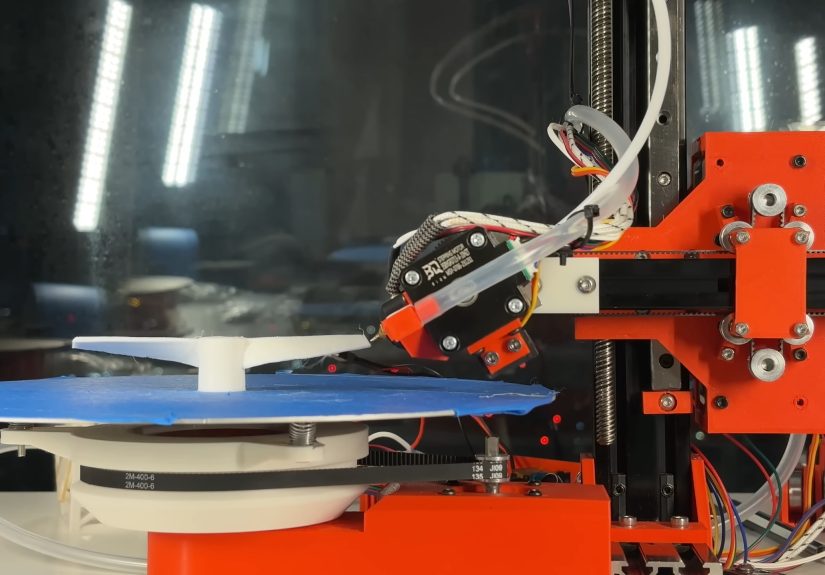
Supportless Overhangs: The Propeller Test
One of the most intuitive demonstrations is printing something like a propeller. The hub can be printed in a conventional, upright orientation. But as the blades sweep outward and start demanding steep overhangs, the nozzle can tilt progressively to match the geometry. This reduces (or even eliminates) the need for support structures under those blades.
It’s not magicphysics still appliesbut it’s a different strategy. Instead of fighting gravity with temporary scaffolding, you change the deposition angle so the part supports itself naturally.
Surface Finish and Strength: More Than Just “No Supports”
Supports get the spotlight because they’re annoying. But multi-axis printing has a second, quieter superpower: curved or non-planar layers can reduce the “stair-step” effect on sloped surfaces. If layers can follow a curve rather than slicing across it like a loaf of bread, the surface can come out smoother.
There’s also the question of strength. With standard FDM, layer lines are often the weak direction. If you can orient deposition paths to better follow stress linesor at least avoid worst-case layer stacking in critical zonesyou can potentially produce parts that resist cracking along layer boundaries. In practice, this depends on material, settings, geometry, and how sophisticated the toolpath planning is. But the door is open.
The Real Boss Fight: Slicing for a Twisting Print Head
Building unusual motion hardware is hard. Teaching software to use it well is harder. Most slicers assume a fixed nozzle orientation and planar layers. Multi-axis printing breaks that assumption, then steals its lunch money.
How Do You Slice Something That Isn’t Planar?
A common workaround in the multi-axis world is a “transform, slice, reverse-transform” pipeline:
- Transform the model into a shape that a conventional slicer can handle (often by “unwrapping” geometry).
- Slice with a mainstream slicer to generate toolpaths (because mainstream slicers are very good at extrusion math).
- Transform the G-code back so those toolpaths map onto the real printer’s kinematics.
It’s clever, slightly mind-bending, and surprisingly practical for certain classes of partsespecially when your printer’s motion is predictable and the geometry plays nicely with the math.
From a Radial Slicer to a More General Non-Planar Approach
Early non-planar slicing tools for rotary/tilting printers often start with “print simple shapes without supports.” That usually means parts that are rotationally friendly (cones, propellers, certain ducts, spirals) and can be described cleanly in polar coordinates.
The next leap is a more generic non-planar slicersoftware that tries to handle a wider range of models by choosing tool orientations and curved-layer strategies automatically. This is where things become both exciting and computationally spicy. A general solution has to consider collisions, nozzle clearance, extrusion stability, cooling, and whether the printer can physically reach all regions of the part at the required angles.
When a “twist-head” printer works well, it’s not just because the nozzle can tilt. It’s because the toolpath decisions are smart enough to make that tilt meaningful.
Engineering Trade-Offs: The Stuff That Doesn’t Fit in a Viral Clip
A twisting print head isn’t only a superpowerit’s also a list of chores that shows up uninvited.
Cooling Gets Weird When the Nozzle Changes Orientation
Standard part-cooling fans assume the nozzle points down and airflow should blast the freshly extruded bead from predictable directions. Tilt the nozzle and suddenly your cooling duct is aiming at the wrong zipcode. One pragmatic workaround is using directed compressed air so cooling can be delivered more flexibly to wherever the extrusion is actually happening.
Cooling matters even more when printing at odd angles: plastic needs to solidify fast enough to hold shape, but not so fast that layer bonding suffers. That balance is already tricky in normal printing; multi-axis just adds extra juggling balls.
Torque, Weight, and the “Wrist” Problem
Tilting mechanisms introduce torque loads and leverage. A small mass far from the pivot can behave like a tiny wrecking ball during motion. That’s why some builders reinforce key parts of the toolhead mountsometimes even fabricating critical components in metalso the system stays stiff and repeatable.
Repeatability is the entire game. When your nozzle is leaning, a tiny error in angle can become a big positional error at the tip. That can mean under-extrusion on one side, collisions on another, or layer lines that drift like they’re trying to escape the part.
Firmware and Calibration Are Not Optional
Multi-axis motion isn’t just “add one more motor.” You need firmware that can interpret kinematics correctly and a calibration process that makes sure “90 degrees” is actually 90 degrees in the real world. Rotary axes, belt coupling, and nozzle tilt all introduce their own quirks: backlash, belt stretch, alignment errors, and the occasional “Why is it doing that?” moment at 2 a.m.
What This Kind of Printer Could Be Great At
Not every part benefits equally from a twisting print head. But certain categories practically wave a flag that says, “Please print me on the weird machine.”
Rotational Parts That Normally Demand Supports
Think impellers, propellers, ducted fans, spiral vases (but with functional geometry), curved handles, ergonomic grips, and housings with internal sweep angles. If the geometry has a natural rotational logicfeatures that repeat around an axis or flow outwardrotary motion can shine.
Objects Where Supports Ruin the Fun
Some prints are technically possible with supports, but the cleanup is so unpleasant that you avoid the design entirely. Multi-axis printing can turn those “I guess I won’t” ideas into “Wait, why didn’t I do this sooner?” projectsespecially for parts where the supported surfaces need to look nice or fit precisely.
Potential Speed Tricks (Because Continuous Rotation Is Smooth)
A rotary table can spin indefinitely without the same stop-start pattern that standard XY moves require. That’s interesting for speed: fewer sudden reversals can mean less vibration and, potentially, faster average motion. A clever toolpath might print a large “rotational core” in a continuous spiral and then add non-rotational details afterward.
This doesn’t automatically make every print faster, but it suggests a new optimization playground for slicer developers and hardware tinkerers alike.
What “Normal Printer” Owners Can Steal from the Twist-Head Idea
Even if you’re not about to build a 4-axis polar printer in your living room (your pets appreciate you), the core lesson applies to everyday printing: geometry and orientation matter.
Design Like You Hate Supports
Supports are a tool, not a lifestyle. When you can, design self-supporting angles, use chamfers instead of sharp overhangs, and orient your part so the most delicate surfaces print cleanly. Small changeslike rounding corners or adjusting anglesoften produce big improvements in reliability and finish.
Split Parts Strategically
If a feature is painful to print in one piece, it may be happier as two or three pieces that assemble later. Multi-axis printing tries to solve the “one piece” problem by changing tool orientation. You can often solve it by changing the assembly strategy instead.
Looking Ahead: The Future Smells Like Firmware Updates and Brilliant Hacks
The most exciting thing about a unique twist-head 3D printer isn’t just the hardware. It’s the idea that desktop printing still has room to evolve in genuinely new directionsespecially when open-source builders experiment with kinematics and share both the wins and the faceplants.
Today, the biggest barrier to widespread adoption is software maturity. Hardware can be built by determined makers; robust, user-friendly multi-axis slicing is a tougher mountain. But progress tends to look like this: a clever workaround becomes a tool, the tool becomes a workflow, and the workflow becomes something normal people can use without needing a PhD in geometry and caffeine consumption.
If that happens, “print head with a twist” won’t sound like a quirky headline. It’ll sound like a feature you expectlike auto bed leveling, input shaping, or “please stop the printer from turning my model into linguine.”
Conclusion
A unique 3D printer with a twisting, tilting print head is a reminder that the “standard” Cartesian layout is just one way to move an extruder through space. By adding rotation at the bed and orientation control at the nozzle, multi-axis machines can print steep overhangs with fewer supports, explore smoother non-planar layers, and potentially unlock new efficiencies for rotationally friendly parts.
The hardware is impressive, but the real story is the ecosystem: clever kinematics, practical cooling solutions, and a growing set of non-planar slicers that translate wild motion into useful G-code. It’s the kind of innovation that makes makers grinbecause it turns “you can’t print that” into “watch me.”
Experiences: What It’s Like to Work with a Twist-Head 3D Printer (and What You Learn Fast)
Watching a twisting print head in action is equal parts engineering demo and oddly satisfying choreography. On a conventional printer, the nozzle is a polite little piston that always points down. On a multi-axis twist-head machine, the nozzle behaves more like a wristleaning, rotating, and “aiming” extrusion where it needs to go. The first experience many builders describe isn’t purely technical; it’s emotional: the moment a steep overhang prints cleanly without supports feels like discovering a cheat code you didn’t know existed.
The second experience is humbling: you realize instantly that multi-axis printing is not “regular printing, plus one axis.” It’s regular printing plus a new personality trait called “geometry consequences.” Even small calibration errors show up dramatically when the nozzle is tilted. A tiny angular misalignment can shift the nozzle tip enough to change bead placement, surface quality, or layer bonding. The practical takeaway is that multi-axis systems reward careful measurement and repeatable mechanical stiffness more than they reward raw speed.
Builders also learn to think differently about model selection. Early wins tend to come from shapes that naturally match the machine’s strengthspropellers, cones, spirals, ducts, and parts that “flow” outward from a center. These models make it easier to understand how radial motion, bed rotation, and nozzle tilt cooperate. Once that mental model clicks, more complex shapes become approachable, but the learning curve often runs through a few sacrificial prints that exist solely to teach you where your assumptions were wrong.
Slicing becomes an experience of its own. Instead of “pick a profile, slice, print,” the workflow can feel like: “choose a strategy, transform geometry, slice, post-process toolpaths, then sanity-check the result.” Many makers describe a new habit formingpreviewing toolpaths obsessively. When the nozzle can tilt, you’re not only checking for gaps or weak infill; you’re checking for clearance, potential collisions, and whether the nozzle will be depositing material into free space at an angle that actually makes sense.
Cooling is another “learn it the hard way” lesson. When the nozzle leans, the airflow you relied on for years may no longer hit the melt zone or the newly laid bead correctly. Some twist-head setups solve this with directed air, including compressed-air approaches that can deliver cooling without the bulky ducts that assume a fixed nozzle orientation. The experience here is practical: prints that look great at one angle can suddenly sag at another if cooling isn’t consistent. Makers often end up tuning fan/air settings specifically for angled segments, not just for the print as a whole.
There’s also a fascinating mindset shift around supports. With a twist-head printer, the goal often becomes “avoid supports by changing deposition direction,” which feels almost like learning to draw in perspective after years of stick figures. You start noticing how features can be “climbed” rather than “bridged,” and how a gentle change in tool orientation can turn an impossible underside into a printable slope. Over time, many users report they begin designing with multi-axis printing in mindchoosing curves and transitions that pair naturally with non-planar toolpaths.
Finally, there’s the social experience: twist-head printers tend to attract curious onlookers and helpful skeptics. People ask the same questionsIs it faster? Is it stronger? Is it reliable?and the honest answer is usually nuanced. The most consistent win is reduced support use and new geometric freedom. Speed and strength depend heavily on the slicer strategy, material, and how well the motion system is tuned. But the most valuable “experience” might be this: working with a twist-head printer makes you better at 3D printing in general, because it forces you to understand what the machine is actually doingand why.